If you’ve never worked on a project involving a thermal remediation solution, it can seem overwhelming. A successful thermal treatment process depends on several factors, many of which involve direct client input, and it’s important to get everything right. In this blog post, I will focus on four key thermal treatment steps you need to take to ensure your project is successful no matter what technology you are considering, no matter what contaminants you are dealing with, and no matter how big your site is.
1. Identify Where the Thermal Treatment Zone is (and isn’t)
Before you do anything at all on the project site, you need to know where the contamination is located. Whenever possible, a proper site evaluation and characterization should be conducted to determine which regions need to be remediated and—just as important—which areas do not. Often, contamination is localized to a few key locations; it is rare for an entire site to need treatment. Every additional cubic yard treated adds cost to your project, so why treat more than you must?

Proper characterization includes the development of an accurate conceptual site model (CSM). The CSM integrates the site’s geology, groundwater flow, and the nature, extent, and the fate of the contaminants into a complete picture to understand where the source zone is. In other words, the CSM shows what needs to be treated to achieve remedial objectives and site closure.
High resolution site characterization (HRSC) is often the backbone of a good CSM. With HRSC, a sufficient density of geologic, groundwater, and contaminant data can be collected quickly and cost-effectively, to clearly identify the appropriate source zone for thermal remediation, and what remaining portions of the contaminated zone can be more efficiently targeted with other technologies (e.g., MNA, ISCO/ISCR, colloidal carbon, thermally enhanced biodegradation, etc.).
2. Set Realistic Goals
Once the thermal target treatment zone (TTZ) has been identified, the next step in the thermal treatment process is to develop reasonable treatment goals, so the project has a definable endpoint. In some cases, local, state, or national regulators may have specific soil and/or groundwater criteria for acceptable concentrations for site contaminants (i.e., remedial cleanup goals). Soil sampling can be used to verify that the area has been sufficiently cleaned.
Absent defined concentration thresholds, an alternate approach commonly used, is to specify that the soil needs to reach a particular temperature for a defined period of time—for example, reaching 100° C for seven days. In other cases, successful thermal treatment of the TTZ is defined as achieving a specified percent reduction in soil and/or groundwater concentrations from their baseline levels prior to the start of treatment (e.g., 90, 95, or 99%).
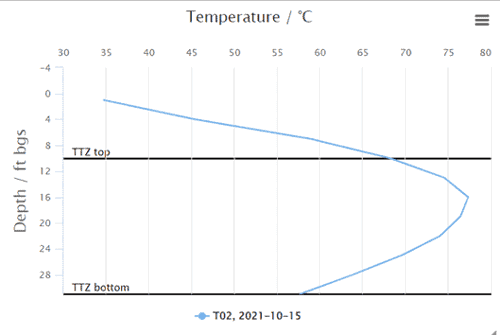
The first figure below shows the temperature profile of a specific location within a TTZ. Near the top, the temperature is lower due to heat losses through the soil to the environment. Temperature increases with depth to a point, but where there is significant groundwater flow cooling will be seen. That’s because the energy input by the thermal remediation technology is carried away by the water, rather than penetrating the soil.

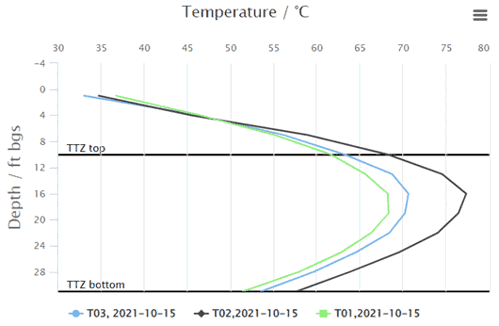
This second figure (below) shows how the temperature profile, although similar, varies from location to location. Therefore, you need to decide what temperature to use to demonstrate compliance and how to calculate and report the temperature. Often, an average temperature for all sensors within the TTZ is sufficient; however, some projects require a minimum temperature to be met, regardless of depth and location.

For sites covering a large area, it is not uncommon to have a faulty reading or two on account of the high numbers of readings taken—which of course can pose an issue with proving you’ve achieved your site goals.
Temperature monitoring systems do have a margin of error and being electrical equipment, for sites covering large areas, it is not uncommon to have a faulty reading or two on account of the high number of readings taken. This should be accounted for when establishing temperature related performance goals.
If a triangular or other geometric pattern is used for the thermal wellfield, these locations equidistant from the surrounding heaters are described as centroids. It is important to remember that the centroid locations are the slowest and last locations within the TTZ to heat up due to being the furthest from the thermal wells. All other portions of the TTZ will achieve and remain at the target temperature many days or weeks before the centroid locations achieve the target temperature.
To account for all of this, performance can be tied to a certain percentage above a given value, for example, 90% of the temperature readings must be above the agreed-upon threshold. This saves the time and cost of having to replace faulty sensors to prove compliance.
3. Develop as Accurate a Starting Mass Estimate as Possible
When the TTZ is established and metrics of when a job is “complete” have been agreed upon, the next step is to develop an estimate of the contaminant mass. The mass estimate is important because it will dictate the above ground equipment needed to treat the fluid, particularly the vapor being pulled out of the ground. For sites with low mass present (typically defined as less than 10,000 to 15,000 lbs), activated carbon is often the most economical treatment approach. For sites with mass estimates between 10,000 and 40,000 lbs a carbon regenerative activated carbon system is usually the preferred treatment option. Thermal oxidizers are typically utilized when the site mass is higher than approximately 40,000 lbs as they are more cost-effective compared to the cost of continual carbon changeouts and disposal of generated free phase product from the steam regenerative activated carbon system.
As most of the mass is generally treated in the vapor phase, having a reliable mass estimate will help ensure the treatment technology is appropriate for the expected conditions. Having to change out carbon more frequently or having an oxidizer running lean and needing to supplement it with extra fuel is never a good thing, but both situations have occurred on account of an incorrect mass estimate.
Despite the importance of correct estimates, the starting mass is often underestimated. This is because no matter how much work goes into site sampling and characterization, there are always unknowns. Perhaps there is a plume of contaminant that is missed, or a pocket of DNAPL/LNAPL that was not discovered during the sampling process. A site’s mass estimate is rarely too high because one can never know truly what is below ground until treatment is underway. Therefore, the vapor liquid treatment systems need to be designed robustly enough to deal with potential unknowns from compounds that weren’t expected to spike in concentrations beyond what the analytical data indicated. Although too much overdesign will add unnecessary cost, a certain amount of extra capacity is warranted, as field conditions often deviate from what the model would predict.
4. Evaluate and Select Optimal Locations for Equipment and Laydown Areas
Finally, once you have your treatment area clean up goals and treatment system designed (including appropriate margins of error), the final step is to locate the equipment that will be needed.
Often, sites have a limited area available. Treating at active facilities presents logistical challenges. The equipment required is often large and needs to be installed on a relatively flat surface, and site preparation is often needed as a prerequisite to the commencement of remediation work. When placing equipment near buildings, be sure to have sufficient offset from the structure to allow for access and maintenance activities. Equipment should be placed as close to existing utilities as possible so that water, gas, and electricity are all readily accessible. Aesthetics also matter; it is often better to place the equipment away from high visibility or high traffic areas, even if that necessitates running additional utility lines. Finally, during the construction phase, have a dedicated laydown area where materials can be brought in and organized prior to being installed.

Knowing your treatment area will ensure all areas of concern are remediated. Setting obtainable, demonstrable treatment goals will ensure an endpoint and not leave treatment open ended, possibly resulting in extended operations and costs. An accurate mass estimate will ensure the remediation system is properly sized and having a dedicated area for the equipment with ease of access will help operations run smoothly. Understanding each of these four thermal treatment steps will ensure your next project runs smoothly and is successful.
If you still have questions about an upcoming thermal project, please don’t hesitate to reach out. We’re happy to assist you in evaluating and working through each of these steps.
04.04.25

