Thermal Conduction Heating 201: Advanced Concepts of TCH
February 07, 2023

If you have been reading our blog posts, you may have already read my colleague Sophia LaRoche’s blog post “An Introduction to Thermal Conduction Heating (TCH)“. In this blog post, I will expand upon some of the topics she discussed and go into further detail about TCH applications. Welcome to TCH 201: Advanced Concepts of TCH.
Want to learn even more about TCH? Watch our webinar “What is TCH and how is it Applied?”
Quick Summary of TCH
Thermal Conduction Heating for soil remediation is a fairly simple process. Heaters are installed in triangular patterns generally built out to hexagons with heating elements that can operate up to 600-800 degrees Celsius (°C). The high temperatures of the heaters and the thermal gradient between the heater and surrounding soil results in the radial conduction of energy and heat to the soil. In close proximity to the heater, the primary mechanism for energy transfer is thermal conduction, while in between the heaters, energy is transferred by both conduction and convection of vapors and water. Because the surface area and soil volume surrounding the heaters increase substantially with distance, temperatures above 100°C are limited to inches adjacent to the heaters, unless the site is designed to reach higher temperatures. Typically, more than 98% of a CVOC TCH site is at 100°C when fully heated.

One of the advantages of TCH is that the thermal conductivity of soil does not vary significantly across all soil types, including fractured rock. At most sites, the property that governs heat transfer and uniformity of heating, thermal conductivity, only varies by a factor of 2-3, including soil above and below the water table and fractured rock. Typical values of thermal conductivity for most sites are in the range of 2.5 Wm-1K-1 for fully saturated porous or fractured material.
The heaters are typically spaced out between 12-17 ft for sites where 100°C is targeted. Heater spacings in this range optimize drilling and construction costs with operational duration and power usage. The heaters also typically extend 5 ft below and above the treatment zone. This is to address heat loss above and below the target interval and ensure uniform heating of the entire treatment zone.
Through heating the soil, the water in the soil along with the contaminants begins to vaporize and steam is generated, which is captured using either horizontal or vertical extraction wells, or through multiphase extraction wells, which also pump water.

TCH and Geology
The appropriate and effective thermal technology and approach are highly dependent on a site’s specific subsurface conditions. When selecting the best technology(s) and designing an efficient thermal remediation system, three important subsurface conditions to look at are:
- Thermal conductivity,
- Electrical conductivity, and
- Hydraulic conductivity and rate of groundwater flux.
For TCH, the thermal conductivity of the materials present within the treatment interval is a major consideration. For example, fractured rock sites tend to have thermal conductivities in the range of 3 to 4 Wm-1K-1. Such sites heat more quickly and allow wider spacing between the heaters and require less energy. However, even dry soils like permeable vadose zone sands, have a thermal conductivity of 1 Wm-1K-1 s and can therefore be heated efficiently and uniformly. Sites with dry, low-conductivity soils may require closer heater spacing and/or longer operational periods but thermal treatment with TCH is still feasible.
This is not the case for electrical resistance heating (ERH). ERH is dependent on the electrical conductivity and resistivity of the soil for heating. As current is passed between ERH electrodes, some of it is converted to heat as a function of the electrical resistance of the soil. If the electrical conductivity is too high, the resistance will be too low, and minimal heat will be generated. If the electrical conductivity is too low (high resistance), then the electrical current will not be able to travel through the soil, and heating will be limited.
In addition, soil electrical conductivity is dependent on soil moisture. If soil moisture is low, or if the soil dries out during ERH (e.g., vadose zone sands), then current flow and heating will cease. Thus, TCH is often a better fit for sites with dry permeable vadose zones that need to be treated.
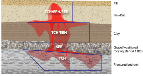
The challenge for TCH (and ERH) can be when the hydraulic conductivity and groundwater flux rates are too high. An example of such conditions would be a gravel aquifer (as can be seen in the figure below), which has a groundwater flux of over 1 ft/day. At such high rates, the thermal output of the TCH heaters is not enough to keep up with the influx of cold water. The water and soil in the target area need to be heated, so if cold water is constantly entering the treatment zone, the rate of temperature increase will be delayed and/or stalled. The solution in such areas is to either reduce the flux of water through the treatment area by installing a physical or hydraulic barrier or to use steam enhanced extraction (SEE), where the steam is injected at a rate sufficient to heat the groundwater influx and the treatment zone and the steam zone limits ongoing groundwater flux.

Looking a little closer at SEE, the important design factor is hydraulic conductivity. If the soil is not conductive enough, then the steam cannot migrate through the site sufficiently and/or uniformly and will fail to adequately heat the targeted treatment area. For SEE, the effective porosity and hydraulic conductivity of most fractured rock sites are too low and for ERH the electrical resistance is too high for effective heating. Fractured rock tends to have a thermal conductivity between 1 and 7 Wm-1K-1, which is ideal for TCH.
TCH Temperature Applications
Besides being flexible and applicable to a wide range of different geologies, TCH is also the most flexible and adept technology for different temperature applications. It can function in all three general heating ranges,
- Low temperature (35 t 90°C),
- Standard heating (target temperature of 100°C) and,
- High temperature thermal remediation (100 to 350°C).
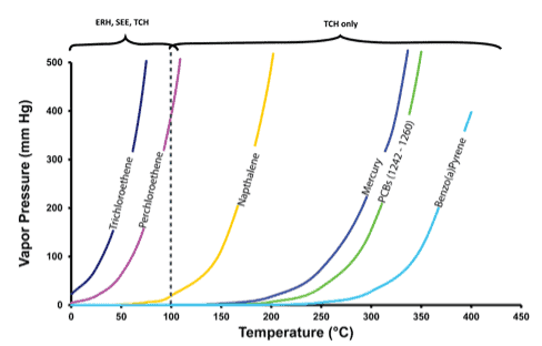
Importantly, TCH is the only thermal technology that works in the high temperature application. This is due to the importance that water has on the performance of ERH and SEE. For ERH, some moisture is required to keep the ground electrically conductive and for power input and heating to continue. But to achieve temperatures above 100°C the soil has to be completely dried out, therefore the electrical conductivity becomes too low and heating ceases for ERH. For SEE, the continued injection of steam/water and the boiling point of water is the limiting factor. Since steam can only get up to temperatures around 100°C (and modestly higher under hydrostatic pressures), it is limited to 100°C treatment. TCH doesn’t have these issues. As mentioned before, as long as the heaters are hot, thermal conduction and heating will occur, regardless of whether the soil is moist or dry. For high temperature applications, the main change is that the heater spacing is tightened significantly, normally around 12 ft, but it can be closer (e.g., 8 to 10 ft) depending on subsurface conditions and target temperature.
For low temperature applications, TCH-style heaters are also ideal. They can easily be turned down to appropriate temperatures to match site conditions, the thermal conductivity of the soil, target temperatures, and remedial timeframes. For example, the heaters can be operated at 100°C to allow heating of the soil to 35 – 90°C without the need for vapor extraction and treatment. SEE isn’t ideal for low temperature approaches because generating the steam isn’t super cost-effective and the injection of steam can easily exceed the target temperatures. ERH can be an effective low temperature technology, however, ongoing current flow through the treatment area limits the ability for active use during treatment. Low temperature heating using TCH can be easily installed below grade and allow active use without any health and safety concerns.
Summary
The most robust and flexible thermal technology is without a doubt TCH. Since it primarily relies on thermal conduction, it can uniformly heat all subsurface materials, both above and below the water table. Its flexibility in different temperature set points and layout patterns makes it adaptable to almost any site condition. However, it isn’t always the perfect solution. In cases of high-water flow, or good electrical conductivity conditions, SEE and ERH may be better options based on cost. The important thing is to consider all these factors when choosing the best heating technology and approach for your site and not try to “shoehorn” a preferred technology to a site purely for business and cost reasons.
If you would like to learn more about TCH and discuss if it’s the right thermal heating technology for your site, watch our webinar, What is TCH and how is it Applied?, and please reach out if you have any questions!

